
 Use a DPDT toggle switch with a flat plastic blade, so you can drill a hole through it to accept the throw linkage. Cut a piece of styrene to fit the application (the one in the picture is 2.25 inches long and 5/8 of an inch wide). Mark the location for the toggles mounting bolt and drill a hole for it (my toggles require a 1/4 inch hole). Drill a hole in the scenery and the roadbed large enough to allow the DPDT switch to slide through. I drill a 1/2 inch hole and then chisel out the corners to make a snug fit for the body of the toggle switch. Prepare the DPDT toggle switch by soldering on six wires (the extra wires can be used for signals or indicator lights). I first slide short lengths of coffee stir straws over the wires and then solder them on the terminals. After the solder has cooled the straws are slid over the joints to insulate them, a twist of the wires bellow the straws will hold them in place.
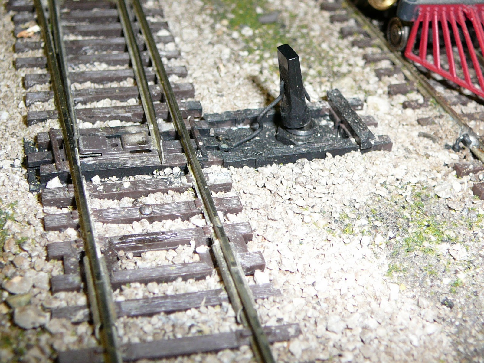
Drill a hole in the blade of the toggle at least half way up so as to miss the steel post in the middle of it. Put the wires and the toggle switch into the hole beside your turnout. Solder one wire from each set of terminals to each of the rails leading to the turnout and the matching center terminal to the insulated frog, thus powering the frog. Be sure to check that you have the proper wire to each of the lead rails so that when you throw the switch the proper rail is powering the frog. The styrene is then positioned under the headblocks (the two ties on either side of the throw bar) and the toggle switch is mounted through the 1/4 inch hole in the styrene. When it is in the correct position the styrene is glued to the headblocks being careful not to glue the throw bar to it, this locks the relative position of the turnout and the toggle switch. The wire link is test fit. First make a 1/8 inch bend up to go through the hole in the throw bar. Then measure the shortest distance to the nut of the togle switch and make another right angle bend up. Bend the wire to the right and then up again as in the illustration. This clears the nut of the toggle switch. Bend the wire at the height of the hole in the toggle switch blade and push it through, this should be a loose fit to allow movement of the wire link. Bend the wire sticking through the blade down and cut off the excess. There should be some play where the wire goes through the toggle blade as the distance the toggle switch throws is more than the points of the turnout move. Needed adjustments can be made by making the bends in the wire sharper. I glue extra ties on the styrene around the toggle switch for looks and paint it all black as in the finished picture.

No comments:
Post a Comment